Maybe having the Raspberry Pi and DC motor combo isn’t enough. Perhaps you want to expand your DIY project portfolio. Read on and try out using DC motors on an Arduino!
Why Use DC Motors on an Arduino
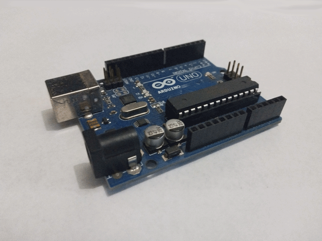
A lot can be said about the differences between a Raspberry Pi and an Arduino. But here are three reasons why you might want to choose the latter:
- Lower cost – you can buy more Arduino boards to drive more DC motors at a lower price.
- Power constraints – if you are running on limited power through a battery or power station, you can run an Arduino on less power than a Raspberry Pi.
- Power interruptions are no issue – an Arduino board can be abruptly cut off from power again and again, and it’ll still work like normal.
Good to know: If you’re planning to choose an ESP32 over an Arduino Uno, remember that there are Arduino shields that can give the latter more functionality. In fact, you could run four DC motors over a single L293D motor driver shield for the Uno.
Why You Need a Motor Driver
Here’s a big warning – don’t you EVER try and put a DC motor directly on your Arduino’s pins, or any other microcontroller’s pins.
There are two reasons for this:
- Prevent damage through counter EMF – counter EMF happens when you turn the motors backward which induces an electromagnetic force that’s so strong that it starts reversing the flow of electricity from GND to the output pin. This can break the output pin you’re using for the motor.
- Avoid overworking pins due to excessive current – to put things into perspective, a hobbyist HCROBO0061 5V DC motor needs 55mA to spin. That’s without a load connected to it. The current requirement will increase if you add a wheel or propeller to it. On the other hand, each output pin on Arduino boards using ATmega328P peaks out at 40mA at maximum. At that point, you’d be maxing out what the microcontroller chip can handle. You should be using about 20mA for continuous output. That’s less than half of what it takes to spin a weak toy motor.
With a DC motor driver, you can get rid of these problems because it isolates your microcontroller’s logic pins from the DC motor itself. The motor driver powers the DC motor too, letting you drive motors needing even up to 100x the Arduino’s current output limit.
Project Requirements
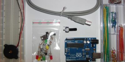
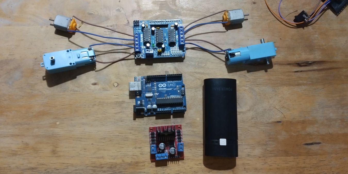
- Arduino – any model will work, although it would be easier to work with an Uno instead
- Motor driver – either the L293D motor driver shield for the Uno or L298N motor driver module for use with other Arduino models
- Jumper wires – for connecting the Arduino to your motor driver
- DC motor – preferably rated 6-12V
- Power supply for the Arduino – either a 9V battery with DC barrel jack or a regular power bank should work
- Power supply for DC motor – a second 9V battery can work as long as it has a DC barrel jack that can connect to on the motor driver’s GND and VCC.
How to Control DC Motors with Arduino
This tutorial outlines two methods of making DC motors work with Arduino.
1. Using L293D Motor Driver Shield
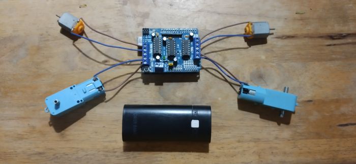
- Copy and paste the following code into the Arduino IDE or PlatformIO. If you plan to use the latter, be sure to add
#include <Arduino.h>.
Note: the following code uses four motors named dcMotor1, dcMotor2, dcMotor3, and dcMotor4.
<span style="color: #808080; font-style: italic;">#include <AFMotor.h> </span><br /><br />AF_DCMotor dcMotor1<span style="color: black;">(</span><span style="color: #ff4500;">1</span><span style="color: black;">)</span><span style="color: #66cc66;">;</span> // This defines the name of the motor <span style="color: black;">(</span>dcMotor1<span style="color: black;">)</span> <span style="color: #ff7700;font-weight:bold;">and</span> port number <span style="color: black;">(</span><span style="color: #ff4500;">1</span><span style="color: black;">)</span>.<br /><span style="color: black;">AF_DCMotor</span> dcMotor2<span style="color: black;">(</span><span style="color: #ff4500;">2</span><span style="color: black;">)</span><span style="color: #66cc66;">;</span><br />AF_DCMotor dcMotor3<span style="color: black;">(</span><span style="color: #ff4500;">3</span><span style="color: black;">)</span><span style="color: #66cc66;">;</span><br />AF_DCMotor dcMotor4<span style="color: black;">(</span><span style="color: #ff4500;">4</span><span style="color: black;">)</span><span style="color: #66cc66;">;</span><br /><br />void setup<span style="color: black;">(</span><span style="color: black;">)</span> <span style="color: black;">{</span><br /> dcMotor1.<span style="color: black;">setSpeed</span><span style="color: black;">(</span><span style="color: #ff4500;">150</span><span style="color: black;">)</span><span style="color: #66cc66;">;</span> // Set the speed <span style="color: #ff7700;font-weight:bold;">for</span> the selected DC motor. <span style="color: black;">Values</span> can <span style="color: #008000;">range</span> between <span style="color: #ff4500;">0</span> <span style="color: #ff7700;font-weight:bold;">and</span> <span style="color: #ff4500;">255</span>.<br /> <span style="color: black;">dcMotor2</span>.<span style="color: black;">setSpeed</span><span style="color: black;">(</span><span style="color: #ff4500;">150</span><span style="color: black;">)</span><span style="color: #66cc66;">;</span><br /> dcMotor3.<span style="color: black;">setSpeed</span><span style="color: black;">(</span><span style="color: #ff4500;">150</span><span style="color: black;">)</span><span style="color: #66cc66;">;</span><br /> dcMotor4.<span style="color: black;">setSpeed</span><span style="color: black;">(</span><span style="color: #ff4500;">150</span><span style="color: black;">)</span><span style="color: #66cc66;">;</span><br /><span style="color: black;">}</span><br /><br />void loop<span style="color: black;">(</span><span style="color: black;">)</span> <span style="color: black;">{</span><br /> dcMotor1.<span style="color: black;">run</span><span style="color: black;">(</span>FORWARD<span style="color: black;">)</span><span style="color: #66cc66;">;</span> // The FORWARD command runs the motor forward.<br /> <span style="color: black;">delay</span><span style="color: black;">(</span><span style="color: #ff4500;">1000</span><span style="color: black;">)</span><span style="color: #66cc66;">;</span> <br /> dcMotor1.<span style="color: black;">run</span><span style="color: black;">(</span>BACKWARD<span style="color: black;">)</span><span style="color: #66cc66;">;</span> // The BACKWARD command runs the motor backward.<br /> <span style="color: black;">delay</span><span style="color: black;">(</span><span style="color: #ff4500;">1000</span><span style="color: black;">)</span><span style="color: #66cc66;">;</span> <br /> dcMotor1.<span style="color: black;">run</span><span style="color: black;">(</span>RELEASE<span style="color: black;">)</span><span style="color: #66cc66;">;</span> // The RELEASE command stops the motor.<br /> <span style="color: black;">delay</span><span style="color: black;">(</span><span style="color: #ff4500;">1000</span><span style="color: black;">)</span><span style="color: #66cc66;">;</span><br /> dcMotor2.<span style="color: black;">run</span><span style="color: black;">(</span>FORWARD<span style="color: black;">)</span><span style="color: #66cc66;">;</span><br /> delay<span style="color: black;">(</span><span style="color: #ff4500;">1000</span><span style="color: black;">)</span><span style="color: #66cc66;">;</span> <br /> dcMotor2.<span style="color: black;">run</span><span style="color: black;">(</span>BACKWARD<span style="color: black;">)</span><span style="color: #66cc66;">;</span><br /> delay<span style="color: black;">(</span><span style="color: #ff4500;">1000</span><span style="color: black;">)</span><span style="color: #66cc66;">;</span> <br /> dcMotor2.<span style="color: black;">run</span><span style="color: black;">(</span>RELEASE<span style="color: black;">)</span><span style="color: #66cc66;">;</span><br /> delay<span style="color: black;">(</span><span style="color: #ff4500;">1000</span><span style="color: black;">)</span><span style="color: #66cc66;">;</span><br /> dcMotor3.<span style="color: black;">run</span><span style="color: black;">(</span>FORWARD<span style="color: black;">)</span><span style="color: #66cc66;">;</span><br /> delay<span style="color: black;">(</span><span style="color: #ff4500;">1000</span><span style="color: black;">)</span><span style="color: #66cc66;">;</span> <br /> dcMotor3.<span style="color: black;">run</span><span style="color: black;">(</span>BACKWARD<span style="color: black;">)</span><span style="color: #66cc66;">;</span><br /> delay<span style="color: black;">(</span><span style="color: #ff4500;">1000</span><span style="color: black;">)</span><span style="color: #66cc66;">;</span> <br /> dcMotor3.<span style="color: black;">run</span><span style="color: black;">(</span>RELEASE<span style="color: black;">)</span><span style="color: #66cc66;">;</span><br /> delay<span style="color: black;">(</span><span style="color: #ff4500;">1000</span><span style="color: black;">)</span><span style="color: #66cc66;">;</span><br /> dcMotor4.<span style="color: black;">run</span><span style="color: black;">(</span>FORWARD<span style="color: black;">)</span><span style="color: #66cc66;">;</span><br /> delay<span style="color: black;">(</span><span style="color: #ff4500;">1000</span><span style="color: black;">)</span><span style="color: #66cc66;">;</span> <br /> dcMotor4.<span style="color: black;">run</span><span style="color: black;">(</span>BACKWARD<span style="color: black;">)</span><span style="color: #66cc66;">;</span><br /> delay<span style="color: black;">(</span><span style="color: #ff4500;">1000</span><span style="color: black;">)</span><span style="color: #66cc66;">;</span> <br /> dcMotor4.<span style="color: black;">run</span><span style="color: black;">(</span>RELEASE<span style="color: black;">)</span><span style="color: #66cc66;">;</span><br /> delay<span style="color: black;">(</span><span style="color: #ff4500;">1000</span><span style="color: black;">)</span><span style="color: #66cc66;">;</span><br /><span style="color: black;">}</span>- Connect the motor driver shield to the Arduino.
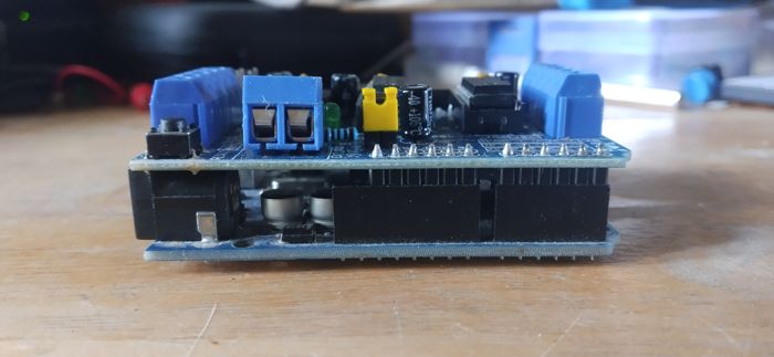
- Check the jumper connector that connects the two PWR pins. Make sure that they are connected. This will bring electricity from the power supply to the Arduino board underneath.
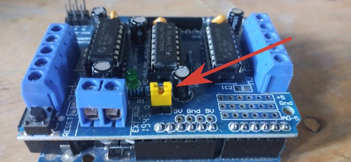
- Connect your motors to the screw terminals marked M1, M2, M3, and M4. You don’t need to connect anything to the GND pin in the middle.
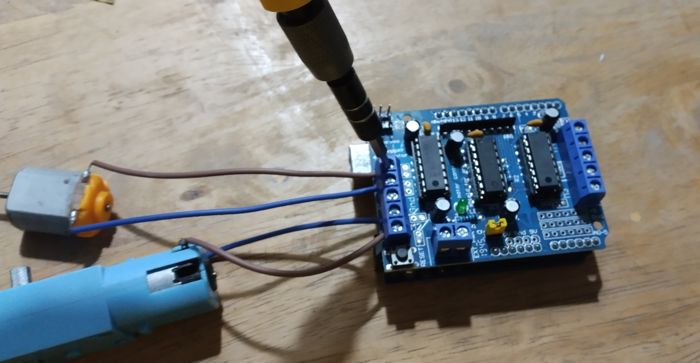
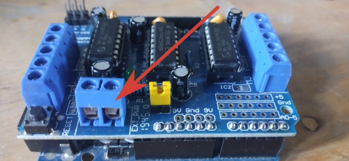
- Connect your power supply to the power terminal. Red wire/cathode goes to M+ and black wire/cathode goes to GND.
Tip: You can attach all kinds of sensors to your Arduino board. Check out the most useful.
2. Using the L298N Motor Driver Module
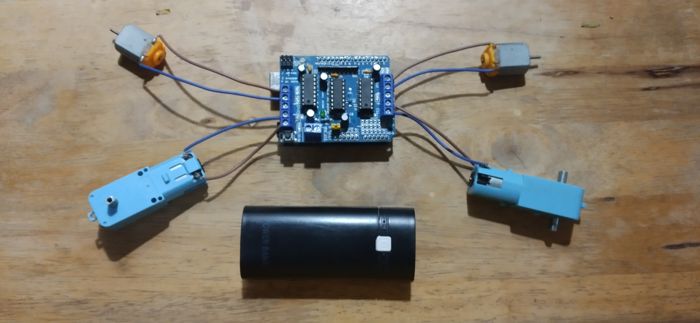
- Copy and paste the following code into your preferred IDE. Similarly, use
#include <Arduino.h>on the first line if you plan to use PlatformIO.
<span style="color: #808080; font-style: italic;">#include <AFMotor.h> </span><br /><br />const <span style="color: #008000;">int</span> EnA <span style="color: #66cc66;">=</span> <span style="color: #ff4500;">5</span><span style="color: #66cc66;">;</span><br />const <span style="color: #008000;">int</span> EnB <span style="color: #66cc66;">=</span> <span style="color: #ff4500;">6</span><span style="color: #66cc66;">;</span><br /><br />const <span style="color: #008000;">int</span> IN1 <span style="color: #66cc66;">=</span> <span style="color: #ff4500;">7</span><span style="color: #66cc66;">;</span><br />const <span style="color: #008000;">int</span> IN2 <span style="color: #66cc66;">=</span> <span style="color: #ff4500;">8</span><span style="color: #66cc66;">;</span><br />const <span style="color: #008000;">int</span> IN3 <span style="color: #66cc66;">=</span> <span style="color: #ff4500;">9</span><span style="color: #66cc66;">;</span><br />const <span style="color: #008000;">int</span> IN4 <span style="color: #66cc66;">=</span> <span style="color: #ff4500;">10</span><span style="color: #66cc66;">;</span><br /><br />void setup<span style="color: black;">(</span><span style="color: black;">)</span> <span style="color: black;">{</span><br /> // First<span style="color: #66cc66;">,</span> define <span style="color: #008000;">all</span> pins <span style="color: #ff7700;font-weight:bold;">as</span> output.<br /> <span style="color: black;">pinMode</span><span style="color: black;">(</span>EnA<span style="color: #66cc66;">,</span> OUTPUT<span style="color: black;">)</span><span style="color: #66cc66;">;</span><br /> pinMode<span style="color: black;">(</span>EnB<span style="color: #66cc66;">,</span> OUTPUT<span style="color: black;">)</span><span style="color: #66cc66;">;</span><br /> pinMode<span style="color: black;">(</span>IN1<span style="color: #66cc66;">,</span> OUTPUT<span style="color: black;">)</span><span style="color: #66cc66;">;</span><br /> pinMode<span style="color: black;">(</span>IN2<span style="color: #66cc66;">,</span> OUTPUT<span style="color: black;">)</span><span style="color: #66cc66;">;</span><br /> pinMode<span style="color: black;">(</span>IN3<span style="color: #66cc66;">,</span> OUTPUT<span style="color: black;">)</span><span style="color: #66cc66;">;</span><br /> pinMode<span style="color: black;">(</span>IN4<span style="color: #66cc66;">,</span> OUTPUT<span style="color: black;">)</span><span style="color: #66cc66;">;</span><br /><span style="color: black;">}</span><br /><br />void loop<span style="color: black;">(</span><span style="color: black;">)</span> <span style="color: black;">{</span><br /> // Add power to motors. <span style="color: black;">The</span> values here <span style="color: #008000;">range</span> between <span style="color: #ff4500;">0</span> <span style="color: #ff7700;font-weight:bold;">and</span> <span style="color: #ff4500;">255</span>.<br /> // We<span style="color: #483d8b;">'ll start by bringing these motors to full power.<br /> analogWrite(EnA, 255);<br /> analogWrite(EnB, 255);<br /> <br /> // Motors will start running as soon as we set a direction.<br /> // The following code will make the motors spin forward and backward consecutively.<br /> const int time = 1200;<br /> digitalWrite(IN1, HIGH);<br /> delay(time);<br /> digitalWrite(IN1, LOW);<br /> digitalWrite(IN2, HIGH);<br /> delay(time);<br /> digitalWrite(IN2, LOW);<br /> digitalWrite(IN3, HIGH);<br /> delay(time);<br /> digitalWrite(IN3, LOW);<br /> digitalWrite(IN4, HIGH);<br /> delay(time);<br /> digitalWrite(IN4, LOW);<br /><br /> // We can control the speed of the motors with the En pins.<br /> // To demonstrate, here is a for loop that will spin both motors gradually faster and slower.<br /> digitalWrite(IN1, HIGH);<br /> digitalWrite(IN3, HIGH);<br /><br /> for (int i = 0; i < 255; i++) {<br /> analogWrite(EnA, i);<br /> analogWrite(EnB, i);<br /> delay(5);<br /> }<br /> for (int i = 255; i > 0; i--) {<br /> analogWrite(EnA, i);<br /> analogWrite(EnB, i);<br /> delay(5);<br /> }<br /> digitalWrite(IN1, LOW);<br /> digitalWrite(IN3, LOW);<br />}</span>- Use female-to-male jumper wires to connect the following pins between Arduino and the L298N motor driver:
- EnA = 5
- EnB = 6
- IN1 = 7
- IN2 = 8
- IN3 = 9
- IN4 = 10.
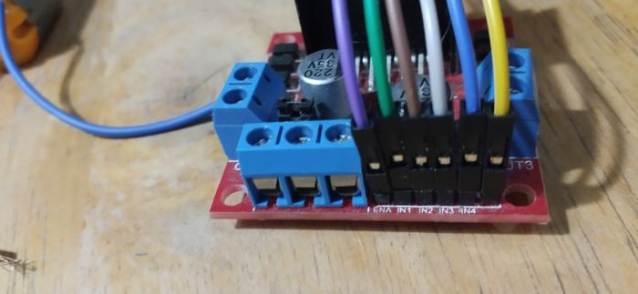
Note: You might have to remove the jumper pins that connect the EnA and EnB pins to the 5V source.
- Connect your motors. The first motor should connect to OUT1 and OUT2 while the second motor to OUT3 and OUT4.
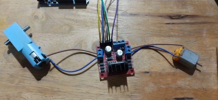
- To power the module, connect the cathode side to +12V and the anode to GND. You can power the Arduino separately by connecting it to a different power source.
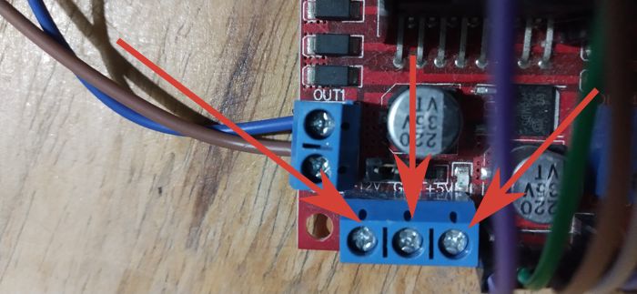
As an alternative, you can also power the Arduino from the +5V pin from the L298N DC motor driver. But do note that this can drain your battery faster.
Frequently Asked Questions
What does it mean when my L298N motor driver module beeps?
Your L298N motor driver module SHOULD NOT beep. If it does, then it’s probably the motors. Your motors might not be having enough electricity to spin, so much that it just vibrates forward and backward instead. If this happens fast enough, it could sound like a long beep to your ears.
Why is my Arduino restarting when I plug in the power to run DC motors?
If you are powering your Arduino through a DC motor driver shield or module, then your Arduino might not be receiving enough electricity to keep running. You can avoid this by powering your Arduino from a separate source that provides a constant stream of 5V and 500mA.
Can I run Arduino DC motors from a USB port?
Absolutely not. Your USB port has barely enough power to run the Arduino board itself. It won’t have enough current to drive a DC motor.
All images by Terenz Jomar Dela Cruz.
